ThompsonJames
Listicle: Understanding Allen-Bradley PLC Logic Symbols
Introduction
If you are interested in industrial automation, you have probably come across the term "Allen-Bradley PLC logic symbols." But what exactly are these symbols and how do they work? In this blog post, we will explore the world of Allen-Bradley PLC logic symbols and their significance in the field of industrial control systems.
Understanding Allen-Bradley PLC Logic Symbols
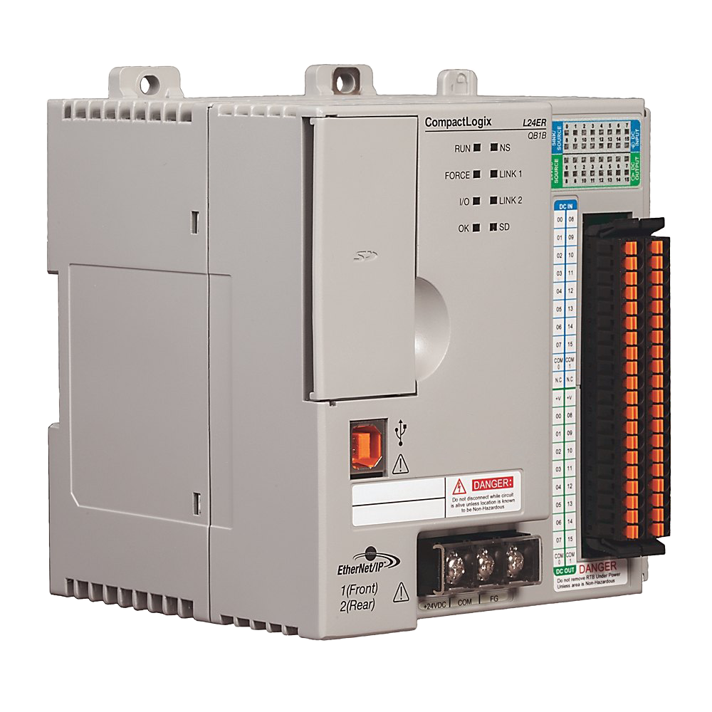
Allen-Bradley is a well-known brand in the industrial automation industry, particularly in the field of programmable logic controllers (PLCs). PLCs are electronic devices used to control and automate industrial processes. They are widely used in manufacturing plants, power stations, and other industrial settings.
PLC logic symbols are graphical representations of different logical operations that can be performed by a PLC. These symbols help engineers and technicians design and program PLCs to perform specific tasks. Each symbol represents a specific function or operation, such as AND, OR, NOT, timers, counters, and more.
Importance of Allen-Bradley PLC Logic Symbols
Allen-Bradley PLC logic symbols play a crucial role in industrial automation. They provide a standardized way of representing logical operations, making it easier for engineers and technicians to communicate and understand PLC programs. By using these symbols, professionals can design complex control systems and troubleshoot issues more efficiently.
Moreover, Allen-Bradley PLC logic symbols are not limited to a single programming language or software. They are widely recognized and used across different PLC platforms, ensuring compatibility and ease of use for professionals working with various PLC brands.
Common Allen-Bradley PLC Logic Symbols
Let's take a look at some of the common Allen-Bradley PLC logic symbols:
1. AND Gate
The AND gate symbol represents the logical AND operation. It takes two or more inputs and produces an output only if all the inputs are true.
2. OR Gate
The OR gate symbol represents the logical OR operation. It takes two or more inputs and produces an output if at least one of the inputs is true.
3. NOT Gate
The NOT gate symbol represents the logical NOT operation. It takes a single input and produces the opposite value as the output.
4. Timer
The timer symbol represents a timer function in a PLC. It is used to introduce time delays or control the duration of specific operations.
5. Counter
The counter symbol represents a counter function in a PLC. It is used to count events or occurrences and trigger actions based on the count value.
Conclusion
Allen-Bradley PLC logic symbols are essential tools for designing and programming industrial control systems. They provide a standardized way of representing logical operations, making it easier for professionals to communicate and understand PLC programs. By using these symbols, engineers and technicians can create efficient and reliable automation solutions for various industries.
Whether you are a beginner or an experienced professional in the field of industrial automation, understanding Allen-Bradley PLC logic symbols is crucial for success in this ever-evolving industry.